Improve Classroom Design and Maintenance with US National CAD Standard V6
Seldom has an update to the U.S. National CAD Standard (NCS) been more applicable to higher education than NCS V6. There are major additional AV and technology symbols for floor plans and reflected ceiling plans that make it easier to design and maintain classrooms and technology space, plus practical guidance to assist in Building Information Modeling (BIM) integration with your current design practices. This article provides an overview of the new AV symbols and gives practical guidance as to what the NCS V6 can do for you.
Beginning the Classroom Design
At the beginning of a new building project, everyone wants to get their ideas into the design process, so committees create pages about how the classroom and the whole educational setting can be integrated into a powerful learning environment. Often, though, these descriptions are not translated into the building as envisioned. Simple graphical sketches, whether in CAD, Visio or Revit, can often communicate more information about the desired technology than pages of descriptions.
Enter NCS Symbols
Symbols are graphical representations of equipment or functional objects. These symbols are used to create CAD drawings or BIM layouts. The NCS is the primary source of technology symbols and abbreviations for architects, contractors and building owners, including colleges. The addition of extensive AV symbols in NCS V6 will greatly enhance your planning.
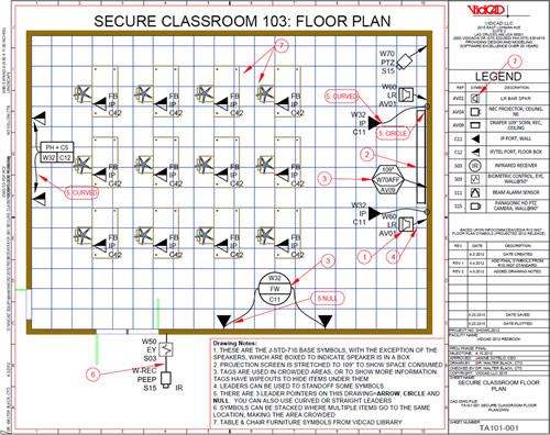
Figure 1: Classroom Floor Plan using NCS AV Symbols with Data-Rich Attributes Describing Technology, Mounting and Legend or Schedule References
In NCS V6, all 1300+ symbols were revised so they are more usable. Also, 72 new and 40 revised symbols were added, including 48 new AV and communications technology symbols. These AV symbols were designed to make it easier for all participants in the design party to understand the educational technology. For instance, compare the v5 (on left) and V6 speakers (on right 2 frames) on Figure 2 and determine which symbols are more understandable. Nearly anyone today would understand the right symbols represent speakers.
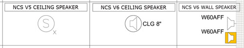
Figure 2: NCS V5 and V6 AV Speakers with Enhancements by AVSymbols.com
Notice also the colored pattern on the wall speaker — this follows Using Color in Symbols, one of two New Symbols Templates in NCS V6. It states: “Color may provide clear distinctions between disciplines in a crowded drawing, especially if used as an accent or background to symbols.” The orange color normally represents AV technology.
These AV symbols are a part of the J-STD-710: Audio, Video and Control Architectural Drawing Symbols Standard, a joint standard of CEA, CEDIA and InfoComm that was approved by ANSI January 2015. The 48 new and unique AV symbols, 25 AV abbreviations and 31 AV Linetypes were approved for inclusion in NCS V6.
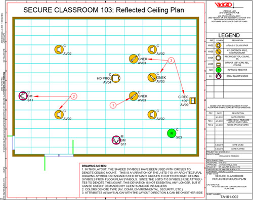
Figure 3: Classroom Reflected Ceiling Plan with NCS AV Symbols Using NCS-Approved Color Backgrounds to Highlight Symbols
As you can see from the attached classroom drawings, AV Floor Plan Symbols simply represent complex technology — as if a symbolic language is spoken between U.S. and international integrators, consultants, architects, engineers and owners; and endorsed by ANSI and US National CAD Standard V6.
Using NCS AV Symbols
All 1300+ symbols, covering all construction disciplines, are included with the purchase of NCS. In addition, the AV symbols are available in the enhanced CAD form shown in the above figures from AVSymbols.com, and a standard version is available from InfoComm, the trade association representing the professional audiovisual and information communications industries.
To use them, simply insert the symbols in your floor plan CAD or Visio drawing. NCS, InfoComm and AVSymbols.com provide extensive guidelines for using data attributes for each type of equipment, as shown in Figure 4.
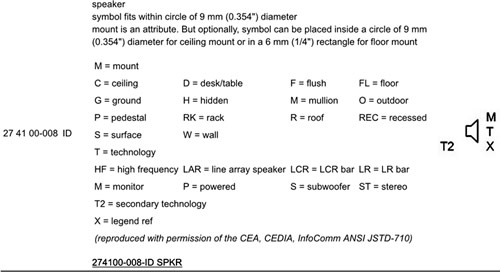
Figure 4: NCS Speaker Symbol with Attribute Definitions and Tips
The NCS AV symbols also provide fast location information and equipment data for maintenance of the classrooms and technical facilities — if the drawings are updated as changes are made.
NCS V6 Provides AV Layer Guidelines
Layers are overlays on the CAD drawing and allow each discipline to add unique layer names based upon the American Institute of Architects (AIA) CAD Layer Guidelines (CLG). When these guidelines are followed, it is easy to turn off disciplines [such as Electrical Power (EP), Fire Protection (FA), Plumbing Piping (PP) or Structural Framing (SF)], to clearly see your AV Equipment [Telecommunications Audio Visual (TA)]. There are many sub-layer naming guidelines, which make it easier to get exactly what you want to see, as shown in Figure 5.
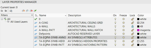
Figure 5: AIA CAD Layer Guidelines for AV Symbols in Classroom Drawing
How Do Layers Work?
Turning unwanted layers on or off is just a click. For example, to turn off the colored AV Symbols Hatching Pattern (TA-EQPM-SYMB-PATT) layer, click the light bulb in the On column. The same holds when going between the floor plan and ceiling plan views: simply click Off the Architectural Ceiling Grid (A-CLNG) light bulb to view the floor plan.
You do not need to know every discipline and subcategory in the AIA CAD Layer Guidelines, but it is imperative that you insist these CLGs be followed in both internal and contract design work.
The Uniform Drawing System (UDS)
If you have a stack of drawings randomly placed on your desk, how would you be able to easily find the drawings for AV Classroom 4401? The NCS Uniform Drawing System (UDS) was created by the Construction Specifications Institute (CSI) to order and number sheets, and provide formatting information, page layout guidelines and floor numbering structures, similar to utilizing the MLA Style Manual or the Dewey Decimal System. All of these were upgraded and simplified in NCS V6. As in the other areas, internal and contract design work should follow these guidelines to easily find a drawing for review.
BIM Implementation Guidelines in V6
With the growing popularity of Building Information Modeling (BIM) in campus construction, NCS created a set of practical guidelines to implement their key features into the BIM workflow. The BIM Implementation Guidelines clarify how to apply the following to BIM:
- CAD Layer Guidelines
- Drawing Set Organization
- Sheet Organization
- Schedules
- Drafting Conventions
- Terms and Abbreviations
- Symbols
- Notations
- Authoring Content Guidelines
- Model Coordination and Delivery Principles
Summary
The US National CAD Standard V6 has a very useful symbols library for classroom AV and technology buildings — making it easier for architects, integrators and campus personnel to communicate their complex technology issues, both in design and maintenance phases. Also, all 1300+ CAD symbols were redrawn and 72 new symbols and 40 revised symbols were added, including the 48 AV symbols.
V6 updated the AIA CAD Layer Guidelines, and these were followed for the NCS AV Symbols library. V6 also updated the Uniform Drawing System to streamline file naming, floor numbering and notation formats. All these features, coupled with the new BIM Implementation Guidelines, will prove a valuable reference to govern all CAD drawings and BIM layouts at your campus.