Electrical Distribution: Designing the Campus Heartbeat
Campus electrical distribution systems support all aspects of campus activity. Understanding the challenges for new and replacement installations is imperative for maintaining university operations and protecting capital investments. This article provides insight into identifying and addressing these challenges.
- By Jared Markle , Andrew Hay
- 08/14/19
The electrical distribution system for a college or university campus represents more than just the utility that keeps the lights on. It is the reliable power that supports world class research, the properly sized system that does not fail in the dead of winter or the peak of summer, and the forward-thinking design that allows for seamless integration of growing and evolving campuses. These upgrades are among the most complex and demanding projects that campuses undergo due to the vital nature of this system to every campus building. Although distribution projects require a very high capital investment, the result is manifested as a maintainable, reliable utility, not a single campus building, sports complex, or other asset that one would typically expect from this type of investment.
Special considerations need to be taken when designing a new or replacement electrical distribution system for a campus including system configuration, service equipment selection, managing underground unknowns, phasing, cost control, and maintaining campus operations. The design approach for a new or expanded campus versus an upgrade to an existing campus has significant differences. The design approach for a new campus focuses primarily on the owner’s program requirements and budget as part of the master plan for the campus, while the approach for an existing campus focuses on phasing, evaluation of existing conditions, and maintaining campus operations throughout construction. This article outlines the important design decisions, construction challenges, and operational considerations that face a college or university when planning an electrical distribution project.
Selecting System Configuration
The configuration for an electrical distribution system is the most important decision in the planning process as it directly affects every aspect of how the system is designed. There are three primary types of distribution system configurations: radial, dual radial, and loop. An example of each of the distribution system connection types is shown in Figure No. 1.
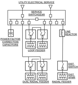
Figure No. 1: An example of a single line diagram showing how typical distribution components can be interconnected in a distribution system.
Radial distribution systems consist of a single electrical feeder to serve individual or multiple buildings loads. The main advantage of utilizing radial feeders is cost. Since only a single feeder is required, smaller ductbanks, less complex service switchgear, and smaller footprint distribution equipment can be used. The disadvantage of radial distribution feeders is the introduction of a single point of failure in the electrical distribution system. Because a single point of failure is the tradeoff for the less costly installation, radial feeders are typically appropriate for non-critical campus buildings or buildings with full generator backup for redundancy.
Dual radial and loop distribution systems both utilize two feeders to serve individual or multiple building loads. The difference between dual radial and loop systems is how the loads are interconnected. Dual radial systems provide two feeders directly to every building on the feeder, resulting in the ability to select from one of the two feeders at each building. Loop feeder systems connect buildings in a series configuration with the feeder “looping” through each building from two separate source breakers. One of the switches in the loop is typically open, meaning that each building is fed from one side of the loop or the other.
The advantage of dual radial feeders is the ability to source select at each building, but the disadvantage is the inability to isolate individual buildings on the feeders. The advantage of loop feeders is the ability to isolate individual buildings to address problems or perform maintenance, but the disadvantage is the inability to source select on an individual building basis. Although both dual radial and loop feeders can be routed in geographically diverse paths to increase system reliability, loop feeders more easily lend themselves to do so. Dual radial and loop feeders are more reliable for campus distribution and typically serve critical buildings or buildings where outages are difficult to coordinate.
Service and Distribution Equipment
Service equipment in an electrical distribution system refers to the equipment at the interface with the electrical utility provider. Distribution equipment refers to the equipment throughout the campus distribution system and at interfaces with campus buildings. This equipment is the most important asset of a distribution project and requires adequate planning to serve a campus’s immediate and future needs. Service and distribution equipment consist of:
- Switchgear
- Distribution switches
- Distribution transformers
- Power factor correction capacitors
- Line reactors
See Figure No. 1 for an example of how the service and distribution equipment is typically connected.
The service switchgear that serves a campus distribution system is typically the largest and most complex piece of equipment in the entire system. The switchgear must not only be coordinated with the electrical utilities’ requirements, which is a challenge in itself, but must also meet the needs of the campus in the budget allotted. Table No. 1 identifies key design decisions for a university to consider when planning a switchgear project.
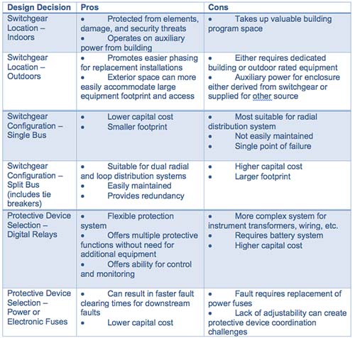
Table No. 1: Switchgear Design Decisions
Distribution switches and transformers provide the capability for downstream switching within a distribution system, overcurrent protection for building transformers, and means for stepping down voltage to usable building levels. The location of this equipment is one of the biggest questions when designing a campus distribution system. There are primarily two options:
- Outdoor, liquid filled switches and transformers located adjacent to the building they serve, or
- Indoor, air-cooled switches and transformers located within the building they serve.
The considerations for locating the distribution equipment indoors or outdoors is similar to that of locating the service switchgear, in that space and cost are typically the determining factors.
Power factor correction capacitors and line reactors are specialized service equipment that are only required if the distribution system is facing low power factor or high fault current challenges. Power factor correction capacitors are most often specified in response to penalties imposed by the electrical utility provider for power factor below a certain number, typically 0.9. Line reactors are typically specified to either limit the available fault current serving an existing system or to limit the fault current that distributed generation can feed back to the utility. Both power factor correction capacitors and line reactors are tools that can be installed to benefit a university financially either by eliminating monthly penalties, allowing for continued operation of otherwise over-dutied equipment, or satisfying utility requirements to operate onsite cogeneration.
Underground Distribution Design
A number of campus electrical distribution systems include routing the electrical feeders underground in concrete encased ductbank between the service switchgear and the campus buildings. Routing the campus feeders underground offers the advantages of reliability, security, and visual appeal versus overhead routing. The biggest challenge with designing and constructing underground ductbank is managing unknowns. The unknowns for underground distribution include existing utility locations, existing larger underground obstructions such as foundations or fuel tanks, and viability of existing ductbank or manholes for reuse.
The best way to manage the unknowns of underground distribution routing is by proactively identifying these risks in the design phase of a project. Although this requires an upfront investment from the college or university, a well-placed $2,000 test pit to identify an existing utility depth can prevent a $50,000 change order in construction to route under rather than over the utility. A distribution design typically includes details for horizontal alignments in the form of site plans, vertical alignments in the form of utility profiles, and cable routing in the form of manhole butterfly diagrams and ductbank sections. The information conveyed in these design drawings is informed based on the field investigation outlined in Table No. 2.
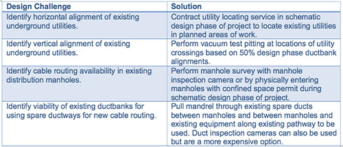
Table No. 2: Distribution Design Challenges and Solutions
In addition to the design details required for an optimal underground distribution system, future planning can be considered with manhole and switch locations to promote future campus growth. A forward thinking distribution design sets a campus up to seamlessly integrate future buildings and other expansion opportunities. A few examples of how a distribution design can be setup to promote future campus growth include
- Locating manholes adjacent to future building locations with modular or separable splices,
- Sizing electrical feeders with spare capacity,
- Providing spare switch outputs in distribution switches, and
- Sizing ductbanks with adequate spare capacity for future feeder installation.
Phasing Upgrade Installation and Maintaining Campus Operations
When designing a replacement for an electrical distribution system, coordination with the project stakeholders is critical. Campus operations’ first responsibility is to maintain service to the campus. Replacement design needs to be detailed and specific to work with the campus, research, and special event schedules. An outage to campus buildings on Commencement Day is not a desirable approach. Outages to buildings are always difficult to schedule as most campuses are always occupied. However, they are especially difficult when they are un-planned. The single radial distribution topology presents a significant challenge to maintenance and upgrades as alternative ways to supply power to the building are not available. The building will need to be placed on a generator or remain without power until service can be restored.
The other topologies provide easier means for redundancy so that feeders and/or buildings can be isolated for maintenance or upgrades, without affecting the other buildings on campus. A dual radial system has the most flexibility for operations as individual buildings can be shifted from one feeder to another, however may present a challenge if maintenance is required on the feeder selector switches. In order to safely maintain the switch, both feeds into it need to be de-energized, which can not be done without additional segment switches on a dual radial system.
The compromise is the loop system which allows for feeder switching and a complete segment of the loop into a building can be isolated upstream, while preserving service to the remainder of the system.
Both a dual radial system and loop system are often designed to allow “closed-transition” or a bump-less transfer from one feeder to another. This option is very beneficial to the operations teams as it allows the reconfiguration of the system without impacts to the building occupants. An item to be aware of in this situation is circulating currents. These are created by the two sides of the system trying to balance the load from one side to the other, creating additional current on the cables. This current could potentially trip protective devices such as fault interrupters and fuses. However, if the system is designed appropriately, this concern can be minimized.
Geographic separation of the redundant feeders also benefits maintenance and operation of the system. Due to the cost of the additional ductbank and manholes, this is not often implemented. The obvious benefit is that the redundant feeders are not within proximity of each other, so failures or construction activities would not impact both, however it also provides the ability to completely de-energize manholes for construction, maintenance, or testing provides a safer work environment.
Cost Control
Whether a new system expansion or a system upgrade or replacement, the budget is always an important aspect as it is with any project. Each system topology reviewed here has different costs associated with them as does switchgear design and subsurface design.
Ways to control budgets are to make sure that cables are not grossly oversized. For one higher education campus in New York State that operates a dual radial system based on a 500kcmil backbone feeder, the campus design standard called for bringing the full-size cables to each building. Through the design process, it was noted that most building transformers did not require the full size of a 500kcmil cable and the transformer protection would limit the circuit ampacity. By reducing the building taps to a 4/0 feeder for 100 buildings, the approximate cost savings was $1.3 million.
Another potential cost-savings measure could be to validate the integrity of the existing underground pathways. PVC conduit in concrete-encased ductbanks is extremely durable and can far outlive the cables it holds. If these conduits can be reused, it will equate to savings for the project and less disruption to the campus environment.
In many cases the cost to replace a distribution system is significant; however, it does not always need to be performed in a single project. It is commonplace for campuses to elect to phase an electrical distribution replacement over 3-10 years. This is a very viable alternative, particularly to campuses that may have funding limitations. The project can be designed to a 35-percent or 50-percent level. Separate packages can then be created to allow the design completion and implementation in a schedule that matches the funding stream.
Summary
In summary, an electrical distribution system design or upgrade is a large but necessary investment that most colleges or universities must make. Designing a successful project includes careful planning in selecting the distribution system type, understanding the distribution components, and proactively identifying and managing underground unknowns. Constructing a successful project requires a detailed phasing approach that maintains campus operations throughout construction and cost control measures throughout the design and construction phases of the project.